C4M Anti-Corrosion Coating for Transformers: ISO 12944 Specification Guide
C4M Anti-Corrosion Coating for Transformers: ISO 12944 Specification Guide
Why C4M Gets Specified — and Why It Often Fails Inspection
C4M is one of the corrosivity categories defined in ISO 12944-2 (Corrosion protection of steel structures by protective paint systems), specifically the "M" designation for marine and coastal atmospheres with moderate-to-high salinity. It is the category most commonly required for substations located near coastlines, offshore platforms' onshore support facilities, and industrial sites in tropical or subtropical marine climates.
The reason C4M is worth a dedicated guide rather than a line item in a general specification: it is also one of the coating requirements most frequently under-delivered by manufacturers who are not set up to consistently hit it. A transformer that looks correctly painted at Factory Acceptance Test can still fail to meet the actual film thickness, adhesion, or surface preparation standard the C4M category requires — and the failure typically only becomes visible 18-36 months after installation, well after the factory warranty conversation is easy to have.
What ISO 12944 C4M Actually Specifies
ISO 12944 defines corrosivity categories from C1 (very low, e.g. heated indoor spaces) through C5 (very high, industrial/marine with high humidity) and CX (extreme, offshore). C4 covers "high" corrosivity — industrial areas and coastal areas with moderate salinity — and the M suffix specifically flags marine/coastal atmospheric exposure as the dominant corrosion driver, as distinct from C4-I (industrial atmosphere without marine salinity).
Key parameters a genuine C4M specification defines:
- Minimum dry film thickness (DFT): typically 200 micrometers (μm) total system thickness for a durability rating of "high" (15-25 years) under ISO 12944-1's durability ranges — though the exact figure should be confirmed against the specific durability range required by the project (medium: 5-15 years, or high: 15-25+ years, both use different minimum DFT tables).
- Surface preparation: typically Sa 2.5 (near-white metal blast cleaning per ISO 8501-1) as a minimum, with a defined anchor profile (commonly 40-75μm) to ensure primer adhesion.
- Multi-coat system: a single-coat or thin two-coat system essentially cannot meet C4M film thickness requirements. A compliant system typically requires three layers: a zinc-rich or zinc-phosphate primer, an intermediate epoxy coat providing the bulk of the barrier thickness, and a UV-stable polyurethane or equivalent topcoat.
- Adhesion: pull-off adhesion testing (per ISO 4624) is the standard verification method, with typical acceptance thresholds around 5 MPa for a multi-coat epoxy/polyurethane system.
The Three Most Common Ways C4M Specifications Fail in Practice
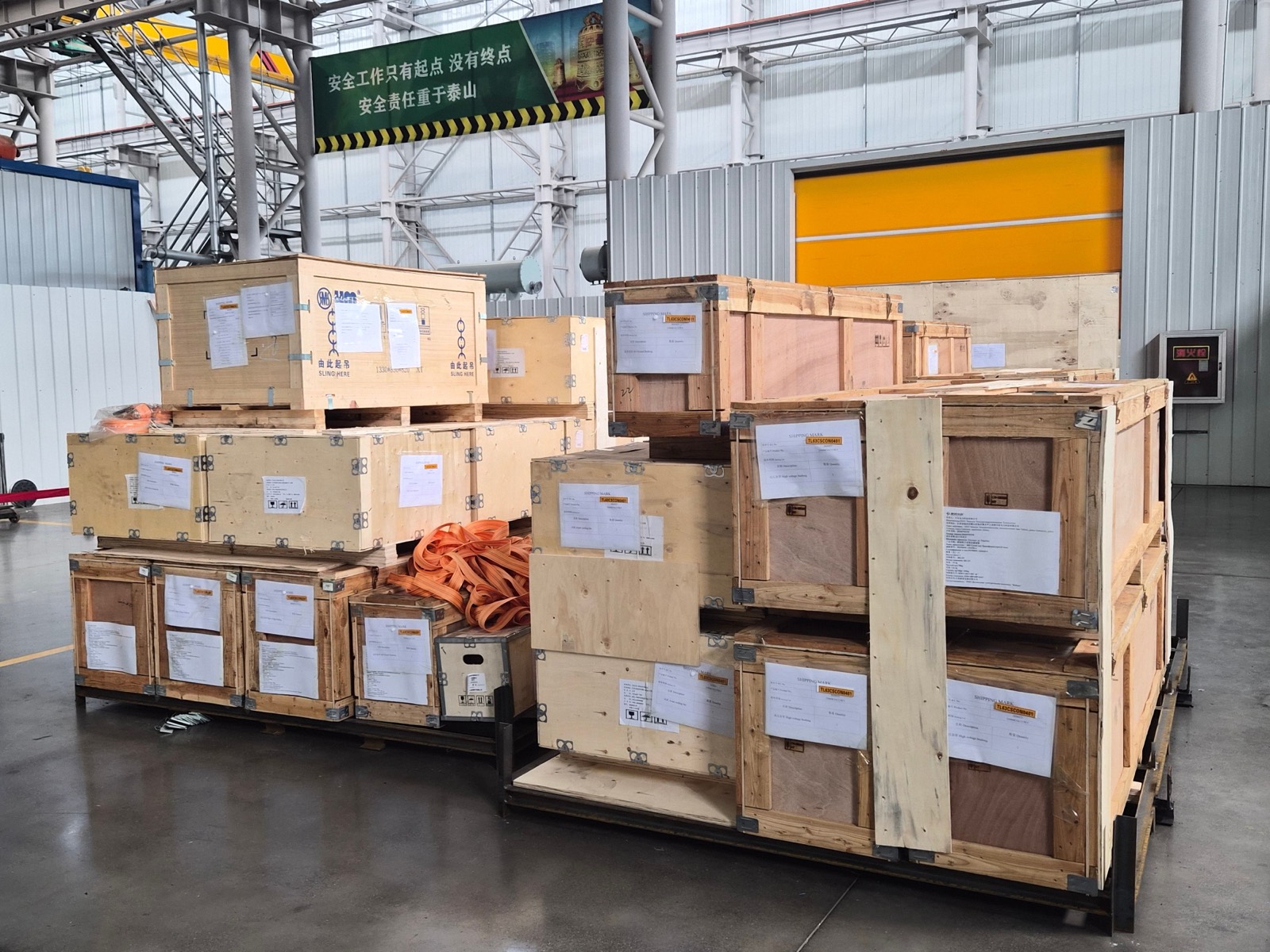
1. Surface preparation shortcuts. Sa 2.5 blast cleaning requires proper abrasive media, equipment, and inspection discipline. A factory under production time pressure may reduce blast time or reuse degraded abrasive, resulting in an anchor profile that is too shallow for proper mechanical adhesion — this failure is invisible without a profile gauge measurement at the time of blasting, and by the time the topcoat is applied, it cannot be verified retroactively except by destructive testing. 2. Film thickness measured in the wrong place, or not at enough points. A transformer tank has flat panels, welded seams, corners, and recessed areas (radiator fins, bracket mounting points) — and coating thickness is naturally uneven across these geometries. A factory reporting a single "average" DFT reading from a few flat-panel spot checks can pass on paper while corners and edges — the areas that actually corrode first — are significantly under-thickness. A genuine C4M verification protocol requires multiple DFT readings (commonly 25+ points per unit) specifically including edges, welds, and recessed geometry, not just flat panel centers. 3. Coating damage during logistics, not manufacturing. Even a correctly applied C4M coating can be compromised during the export packaging, loading, ocean freight, and inland transport chain — impact damage from improper cradling, moisture ingress during a multi-week sea voyage, or abrasion from inadequate protective wrapping. A C4M specification that stops at the factory gate and does not extend to a matched export packaging and logistics protocol leaves a real gap between "passed FAT" and "arrived intact."Verification Checklist for a C4M Order
Before accepting a transformer specified to C4M, request documentation covering:
- Surface preparation record: blast method, abrasive type, achieved anchor profile (μm), inspected per ISO 8501-1 grade
- Coating system datasheet: each layer's product, nominal DFT, and total system DFT
- Dry film thickness inspection report: minimum 25 measurement points per unit for a typical MV/HV transformer tank, explicitly including weld seams, corners, and recessed areas — not just flat panel averages
- Adhesion (pull-off) test results per ISO 4624, with pass/fail threshold stated
- Holiday/pinhole detection results (electrical continuity testing for coating film integrity, particularly relevant on buried or submerged components)
- Export packaging specification: cradle design, VCI (Volatile Corrosion Inhibitor) treatment for exposed surfaces, moisture barrier wrapping, and shock/tilt indicators
How This Applies Beyond Coastal Substations
While C4M is most commonly discussed in the context of coastal or offshore-adjacent substations, the same verification discipline applies to any project where the destination environment involves elevated humidity, industrial pollutants, or de-icing salt exposure (e.g. some industrial sites, or northern climates with heavy road-salt use near substation yards) — the corrosivity category may differ (C4-I for industrial-only exposure, C5-M for the most severe marine/offshore conditions), but the verification approach — documented surface prep, multi-point DFT measurement, adhesion testing, and export packaging protocol — is the same.
For a worked example of how this specification and verification process applies to an actual coastal substation project, see our [C4M anti-corrosion power transformer reference project](/cases/southeast-asia-substation-c4m/), covering 110kV/22kV, 50MVA units engineered to a 220μm total DFT system for a coastal substation with year-round humidity above 90% RH.
How Apex Power Systems Verifies C4M Compliance
Coating verification is part of our standard quality-control scope for any project specifying C4M or higher corrosivity categories:
- Factory selection restricted to partners with a dedicated coating workshop, controlled application environment, and documented C4M/C5-M export history
- Pre-production coating trial on sample panels before full production begins
- Full DFT inspection at 25+ points per unit using calibrated Elcometer gauges, with results documented and shared before shipment
- Export packaging matched to the coating specification — VCI treatment, moisture barrier wrapping, and impact-protected cradling — not a generic packaging default
If your project specification includes a C4M, C4-I, or C5-M coating requirement, submit your specification and our engineering team will confirm the coating system and verification protocol before production begins.
For technical questions, you can also chat with our engineering team directly on WhatsApp: [+86 132-0157-1341](https://wa.me/8613201571341).
---
*This article provides general technical guidance based on ISO 12944 coating standards. Specific durability ranges, DFT requirements, and inspection protocols should be confirmed against the exact project specification and destination environment. Always verify coating documentation directly with the manufacturer before final acceptance.*
Need specific technical advice for your project?
Submit your project details (voltage class, capacity requirements, installation environment) and our engineering team will provide tailored transformer selection recommendations and budget references.
Submit Your ProjectRelated Articles
Quality Verification for Overseas Transformer Procurement: From Factory Audit to FAT
2026-06-12
Procurement GuideHow to Verify a Chinese Transformer Factory Before You Procure
2026-08-07
Technical SpecificationISO 12944 Corrosion Classes Explained: C3 vs C4 vs C5M vs C5I for Transformer Coating
2026-08-25
Need Technical Support?
Our engineering team is ready to help with transformer selection, quality verification, and technical specification questions.
Get Expert Advice